A Practical Approach for Modeling a Bevel Gear
By A Mystery Man Writer
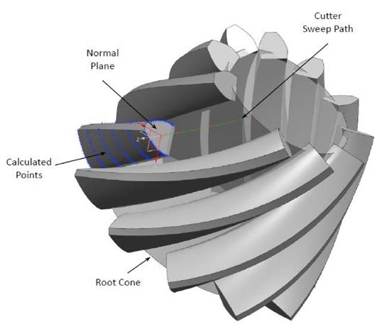
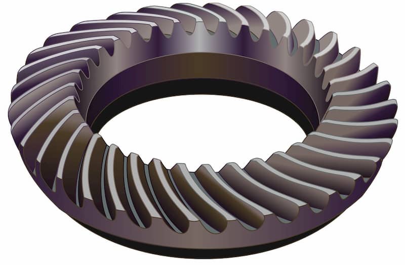
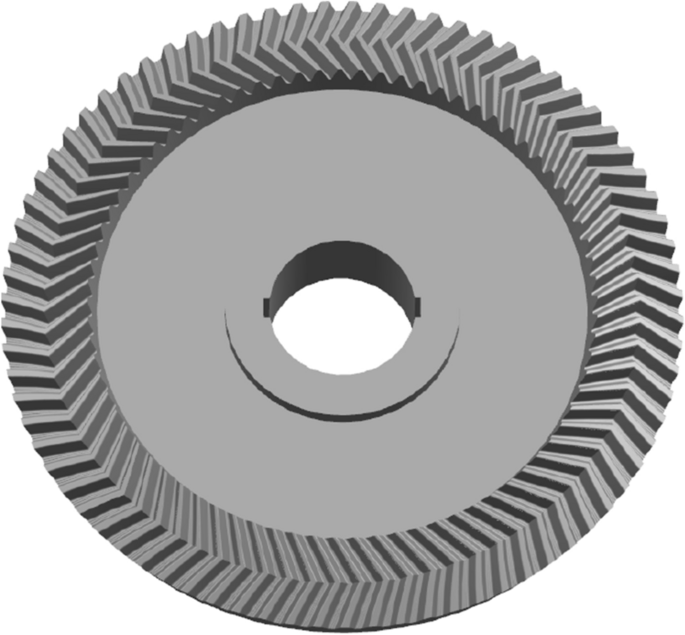
The geometry of the bevel gear is quite complicated to describe mathematically, and much of the overall surface topology of the tooth flank is dependent on the machine settings and cutting method employed. AGMA 929-A06 — Calculation of Bevel Gear Top Land and Guidance on Cutter Edge Radius — lays out a practical approach for predicting the approximate top-land thicknesses at certain points of interest — regardless of the exact machine settings that will generate the tooth form. The points of interest that AGMA 929-A06 address consist of toe, mean, heel, and point of involute lengthwise curvature. The following method expands upon the concepts described in AGMA 929-A06 to allow the user to calculate not only the top-land thickness, but the more general case as well, i.e. — normal tooth thickness anywhere along the face and profile of the bevel gear tooth. This method does not rely on any additional machine settings; only basic geometry of the cutter, blank, and teeth are required to calculate fairly accurate tooth thicknesses. The tooth thicknesses are then transformed into a point cloud describing both the convex and concave flanks in a global, Cartesian coordinate system. These points can be utilized in any modern computer-aided design software package to assist in the generation of a 3D solid model; all pertinent tooth macrogeometry can be closely simulated using this technique. A case study will be presented evaluating the accuracy of the point cloud data compared to a physical part.

PDF] A Practical Approach for Modeling a Bevel Gear
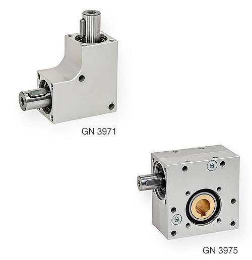
High Torques thanks to Compact Bevel Gear Boxes and Worm Gear Reducers

PDF] A Practical Approach for Modeling a Bevel Gear
Gear Skiving—A Step Changing Manufacturing Process Applicable to Multifunctional 5-Axis Machine Tools

Modification of the Spindle Head for a Milling Machine with Increased Load Capacity Drive

Three dimensional solid modeling of involute straight bevel gear – ZHY Gear
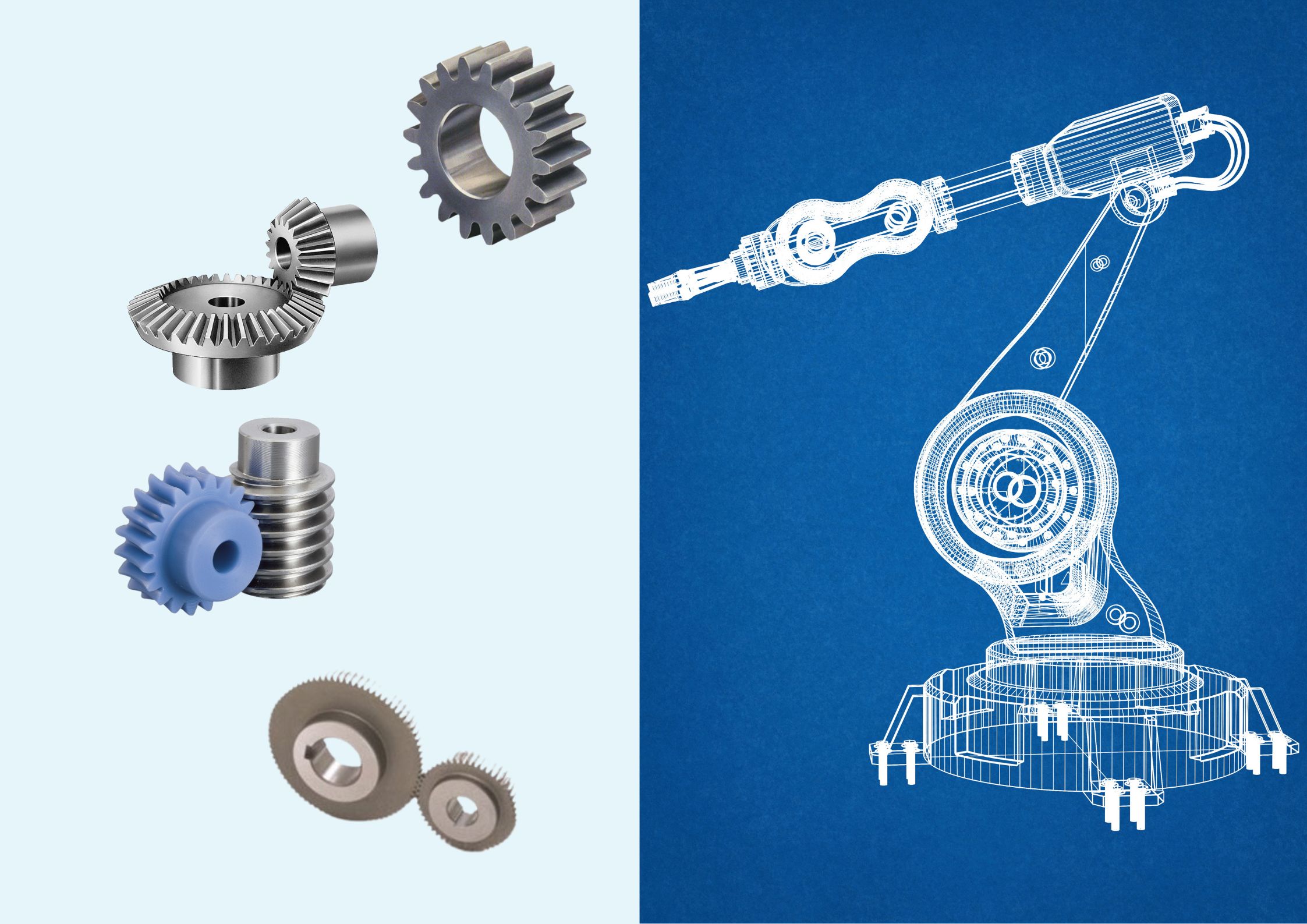
Gears for Robotic Application
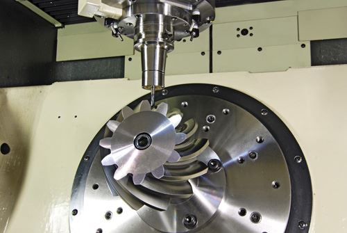
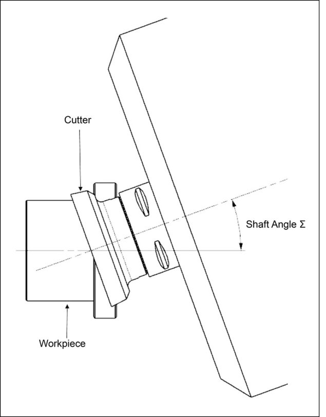
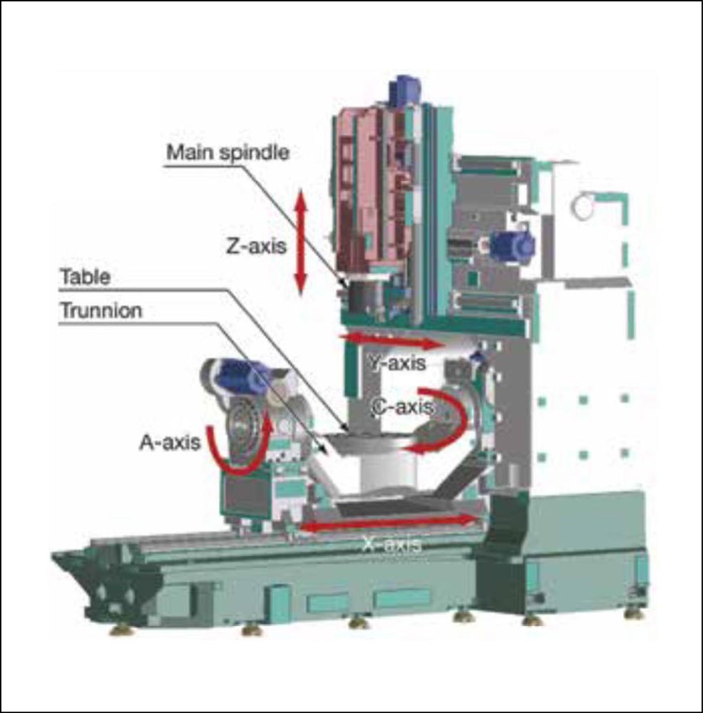
Cutting Spiral Bevel Gears On A Five-Axis Machining Center
Gear Skiving—A Step Changing Manufacturing Process Applicable to Multifunctional 5-Axis Machine Tools

Make 3d CAD Model of Spiral Bevel.115110106, PDF, Gear
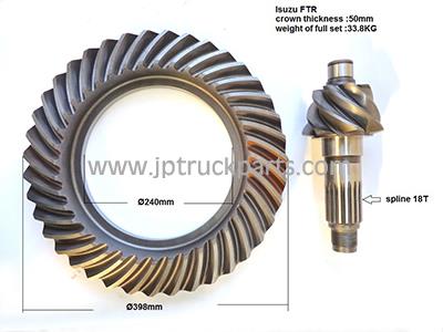
- Truck Parts FTR CXZ truck bevel gear crown wheel and pinion ratio 7*39
- Crown Wheel Pinion Gear 1683757 Fit for MF 240 : : Industrial & Scientific

- Types of Gears, Gear Parameters & Tooth Profiles
- Noncircular bevel gears with cosine tooth profile and helix tooth

- The designing and modeling of equal base circle herringbone curved bevel gears
- In The Style x Liberty leather look flare pants in black
- Oner Active knowingly making sheer leggings… and then people DEFENDING her for that?! : r/gymsnark

- Beyond The Black Rainbow – film review

- Cotton Dresses - Cotton Midi Dresses, Cotton Summer Dresses & More

- Flower Bali Underwire Bra Style - 0180 Size 32B for sale online